- Volume potentiometer resistor value ? Generally 10KOhms.
- Linear or logarithmic ?
- Output number : 1 to 10 ?
- Clamping resistor value in case of 2 potentiometer outputs ?
- MIDI channel number requested (configurable by software)
- Kind of MIDI output control : ControlChange ? ProgramChange ?
- Number of volume inputs ?
- Number of pistons inputs ?
- Total volume + pistons inputs must be 10 maximum.

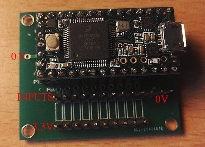
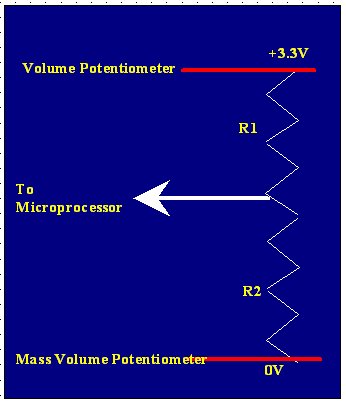
In case of 3 potentiometer ouputs, control is done by the middle of the potentiometer. (Marked INPUTS in RED) . In this case, all the MIDI dynamics is achieved : from 0 to 127.
In the case of 2 outputs pins potentiometer : one can loose values in the upper part of the 0-127 range. Depending of the clamping resistor value.
One can refine the control commande by a software logarithmic table.
In the case of a 2 outputs potentiometer, the R1 clamping résistor is placed on the board. Générally : 1 KOhms.
In the case of a 3 outputs potentiometer, R1 et R2 are of course contained on the potentiomer.
NOTA : One can also solder in parallel a 100K Ohms resistor, in order to avoid unattended MIDI controls, if the pedal shoe is disconnected. (The hot input pin beeing unconnected).
NOTA 2 : By security, the positive pole of the potentiometers are connected to the TEENSY 3,3V outputs (marked in RED 3,3V)and not to the 5V. Otherwise, all the dynamics is not achieved. (No electric damage in case of 5V connection).
